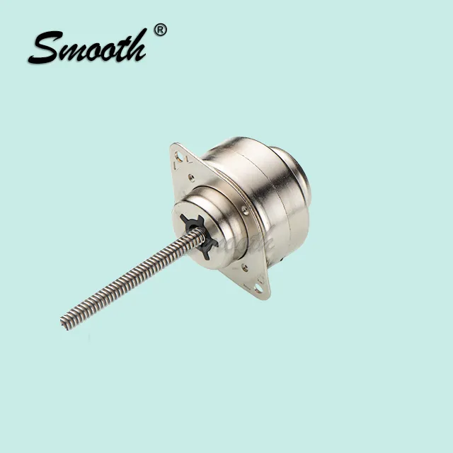
Picking the right motion component can feel overwhelming when a catalog lists dozens of models with different stroke lengths, torque ratings, and step angles. This guide breaks the selection process into manageable pieces so that choosing a stepper linear actuator becomes a matter of matching known project requirements to available specifications, rather than guessing and hoping for the best. Working through each factor methodically, rather than jumping straight to a familiar model from a previous project, helps ensure the final choice actually fits the specific mechanical and environmental demands of the current application rather than simply repeating past decisions out of habit.
Start With Load and Force Requirements
Before anything else, calculate the actual force the actuator needs to move, including friction, gravity, and any resistance from the mechanism itself. Underestimating load is one of the most common mistakes engineers make, leading to actuators that stall or overheat under real-world conditions. It helps to add a safety margin of at least twenty percent above the calculated force to account for wear and unexpected resistance over the unit’s lifetime. Building this margin in early avoids the awkward situation of discovering, months into production, that a component sized right at the theoretical minimum can no longer keep up once bearings wear slightly or lubrication thins with age. Consulting with the manufacturer’s application engineers at this stage, rather than relying solely on internal estimates, often reveals real-world friction factors that are easy to overlook on a first pass.
Define the Required Travel Distance and Speed
Stroke length and speed go hand in hand. A longer stroke paired with a high-speed requirement often means a coarser lead screw pitch, which trades off some resolution for faster travel. Projects that prioritize fine positioning over speed should lean toward a finer pitch, while those needing rapid cycle times may accept slightly less precision in exchange for throughput. Mapping out the full range of motion the mechanism will actually use in practice, rather than just the theoretical maximum stroke, often reveals that a shorter, more economical actuator will comfortably meet the real requirement. It also helps to sketch out the full motion profile, including acceleration and deceleration phases, since the average speed across a cycle is often quite different from the peak speed alone.
Consider the Operating Environment
Temperature extremes, dust, moisture, and vibration all influence which actuator housing and sealing rating make sense. A clean indoor lab setting has very different demands than an outdoor solar tracking mount or a food processing line that requires washdown-rated components. Matching the environmental rating to the actual deployment conditions prevents premature failure. It also pays to consider conditions the equipment might encounter only occasionally, such as a cleaning crew using a pressure washer nearby, since these edge cases often determine real-world lifespan more than the everyday operating environment alone. Talking directly with maintenance staff who will service the equipment day to day often surfaces practical environmental concerns that a purely theoretical review of the installation site might otherwise miss.
Match Step Resolution to Precision Needs
Not every application needs microstepping resolution measured in fractions of a degree. Overspecifying resolution adds cost without adding real value, while underspecifying it can leave a project unable to meet tolerance requirements. Reviewing the target tolerance for the finished application, and working backward to the needed step resolution, keeps the specification realistic. This backward-calculation approach also helps when comparing quotes between suppliers, since it becomes much easier to identify which vendor is offering genuinely comparable performance rather than simply a higher number on a spec sheet. It is also worth checking whether the mechanical system introduces any backlash or compliance of its own, since even a perfectly precise actuator cannot overcome slop elsewhere in the drivetrain.
Plan for Control Compatibility
The actuator is only half of the system; the driver and controller need to speak the same language. Confirming voltage requirements, current ratings, and whether the actuator uses unipolar or bipolar wiring saves significant troubleshooting time during integration. Reaching out to the manufacturer’s technical support team early in the design process, rather than after components have already been ordered, often surfaces compatibility considerations that aren’t immediately obvious from a datasheet alone. Requesting a sample wiring diagram from the manufacturer and comparing it directly against the intended driver board is a small step that frequently saves hours of confusion during commissioning.
Finalizing the Decision
Once load, travel, environment, resolution, and control compatibility are all mapped out, the shortlist of suitable stepper linear actuator models usually narrows quickly. At this stage, it also helps to review documented specifications directly from the manufacturer rather than relying on assumptions carried over from a previous project. Every application is a little different, and a few extra minutes spent confirming specifications against real requirements can prevent costly redesigns down the road, particularly on projects where the actuator will run continuously for years without easy access for replacement. Documenting the reasoning behind the final specification also proves valuable later, when a future engineer revisits the design and needs to understand why a particular model was chosen over the alternatives.